TOP03 Basic Examples
This section collects some simple examples that show how to build a μPanel project using our SCF-TOP03 Arduino-compatible Wi-Fi board.
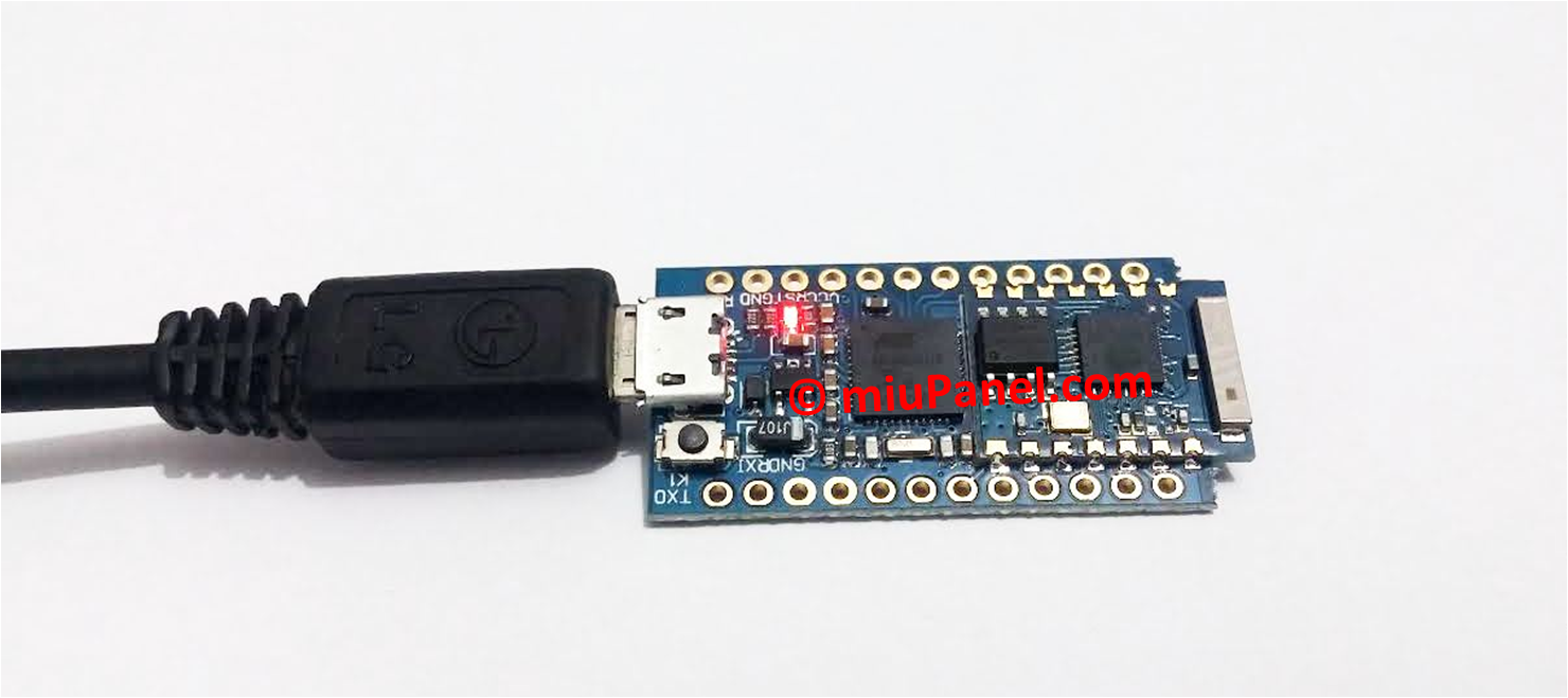
Before to test the following examples, we suggest you to discover here the details of the SCF-TOP03 wi-fi board.
1. LED Blink
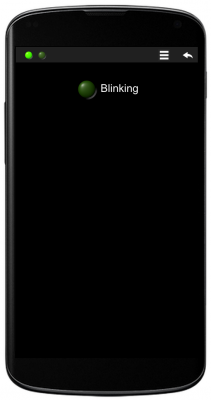
In this example Arduino will create a simple panel with a LED and it will blink it at 1 Hz.
Hardware
- TOP03 Arduino Compatible Wi-Fi Board
- Power supply (for example a 5V smartphone charger with micro-USB jack)
µPanel definition
Using the Online Panel Simulator you can easily design and check the panel layout before loading it on Arduino.
The panel definition is minimal, it contains only one LED with its label.
*15/L1G:0:Blinking;
TOP03 Code (Arduino Lilypad USB)
/**************************************************
 --- IMPORTANT ---: before to load your sketch, please select the board "LilyPad Arduino USB" in the boards menu.
 If you have accidentally select another board, and load your sketch, read here:
 www.arduino.cc/en/Guide/ArduinoLilyPadUSB

 Connection table:

 * ESP8266  Arduino
 * GPIO0    12
 * ENABLE   13
 * RX       TX
 * TX       RX
 * GND      GND

 About Serial
 The "Lilypad USB" (and T) use "Serial1" to communicate via TTL serial on pins 0 (RX) and 1 (TX). "Serial" is reserved for USB CDC communication.

***************************************************/

#define ESP_PROGRAM_PIN  12
#define ESP_ENABLE_PIN   13

void setup() {

  Serial1.begin(57600);        // Initialise serial 1 (WiFi Module)

  pinMode(ESP_ENABLE_PIN, OUTPUT);
  pinMode(ESP_PROGRAM_PIN, OUTPUT);
  pinMode(ESP_PROGRAM_PIN, OUTPUT);

  // Set ESP module in RUN mode on reset
  digitalWrite(ESP_PROGRAM_PIN, HIGH);
  digitalWrite(ESP_ENABLE_PIN, HIGH);

  delay(5000);                 // Let's the module start
  // Discharge old partial messages
  Serial1.println("");
  // Enable real-time response
  Serial1.println("$PING 200");
  // Send Panel (Single Green LED, 150% size on new line with text Blinking)
  Serial1.println("$P:*15/L1G:0:Blinking;");

}

void loop() {

  delay(500);                 // Wait 0.5 s
  Serial1.println("#L11");    // Turn ON LED 1
  delay(500);                 // Wait 0.5 s
  Serial1.println("#L10");    // Turn OFF LED 1
}
2. One-digit chronometer
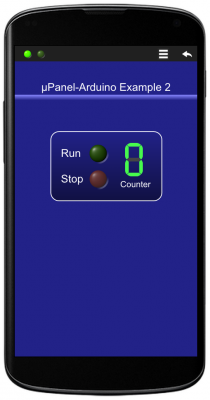
In this example a simple chronometer is implemented using one 7-segment LCD. Arduino will increment a variable at 1 Hz rate and will update the display state accordingly.
Hardware
- TOP03 Arduino Compatible Wi-Fi Board
- Power supply (for example a 5V smartphone charger with micro-USB jack)
µPanel definition
The panel definition is very simple and quite similar to the first one presented in Design Examples, just an additional text has been added in order to display the example reference.
D!228;*10/T*15:μPanel-Arduino Example 2;{%100,3!88F,228}/20{-3r30p20!228,114*15{T:Run;|L1G:0;_T:Stop;|L2R:0;}|{^*8L35:0;_T:Counter;}}
TOP03 Code (Arduino Lilypad USB)
/*************************************************
 --- IMPORTANT ---: before to load your sketch, please select the board "LilyPad Arduino USB" in the boards menu.
 If you have accidentally select another board, and load your sketch, read here:
 www.arduino.cc/en/Guide/ArduinoLilyPadUSB

 Connection table:

 * ESP8266  Arduino
 * GPIO0    12
 * ENABLE   13
 * RX       TX
 * TX       RX
 * GND      GND

 About Serial
 The "Lilypad USB" (and T) use "Serial1" to communicate via TTL serial on pins 0 (RX) and 1 (TX).
 "Serial" is reserved for USB CDC communication.
***************************************************/

#define ESP_PROGRAM_PIN  12
#define ESP_ENABLE_PIN   13

void setup() {

  Serial1.begin(57600);        // Initialise serial 1 (WiFi Module)

  pinMode(ESP_ENABLE_PIN, OUTPUT);
  pinMode(ESP_PROGRAM_PIN, OUTPUT);

  // Set ESP module in RUN mode on reset
  digitalWrite(ESP_PROGRAM_PIN, HIGH);
  digitalWrite(ESP_ENABLE_PIN, HIGH);

  delay(5000);                 // Let's the module start

  // Discharge old partial messages and activate real-time response
  Serial.println("\n$PING 200");

  // Send Panel (split in 2 strings for convenience)
  Serial1.print("$P:D!228;*10/T*15:μPanel-Arduino Example 2;{%100,3!88F,228}/20");
  Serial1.println("{-3r30p20!228,114*15{T:Run;|L1G:0;_T:Stop;|L2R:0;}|{^*8L35:0;_T:Counter;}}");

  // Turn ON LED 1
  Serial1.println("#L11");
}

long int n = 0;  // Define and initialise counter

void loop() {

  // Wait 1 s
  delay(1000);

  // Set LED 3 State and increment counter
  Serial1.print("#L3");
  Serial1.println((n++ % 10),DEC);

}
3. Switch a LED On/Off
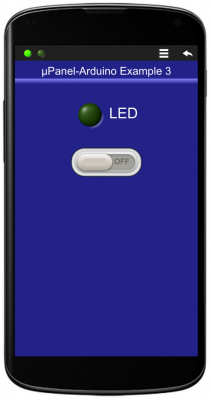
In this example a switch and a LED will be placed on the Panel. Arduino will be waiting for the user to change the switch state and will update the LED status accordingly. This is the first example where Arduino has to receive messages sent by the Panel, thus, we have to connect the Arduino Rx line and include into the Arduino code the functions to read the incoming messages.
Hardware
- TOP03 Arduino Compatible Wi-Fi Board
- Power supply (for example a 5V smartphone charger with micro-USB jack)
µPanel definition
The panel definition includes a text for the panel title, a standard green LED and a On/Off switch of type 2.
D!228;T*15:μPanel-Arduino Example 3;{%100,3!88F,228}*20/L1G:0:LED;*10/W1:0;
TOP03 Code (Arduino Lilypad USB)
/**************************************************
 IMPORTANT: before to load your sketch, please select the board "LilyPad Arduino USB" in the boards menu.
 If you have accidentally select another board, and load your sketch, read here:
 www.arduino.cc/en/Guide/ArduinoLilyPadUSB

 * Connection table:
 * ESP8266  Arduino
 * GPIO0    12
 * ENABLE   13
 * RX       TX
 * TX       RX
 * GND      GND

 About Serial
 The "Lilypad USB" (and the board derived from it) use "Serial1" to communicate via TTL serial on pins 0 (RX) and 1 (TX).
 "Serial" is reserved for USB CDC communication.

 ***************************************************/

#define ESP_PROGRAM_PIN  12
#define ESP_ENABLE_PIN  13

String Msg;

void setup()
{
  Serial1.begin(57600);
  Serial.begin(57600);

  pinMode(ESP_ENABLE_PIN, OUTPUT);
  pinMode(ESP_PROGRAM_PIN, OUTPUT);

  // Set ESP module in RUN mode on reset
  digitalWrite(ESP_PROGRAM_PIN, HIGH);
  digitalWrite(ESP_ENABLE_PIN, HIGH);

  // Let uPanel to start
  delay(5000);

  // Discharge old partial messages and activate real-time response
  Serial1.println("\n$PING 200");

  // Send Panel (A LED and a Switch)
  Serial1.println("$P:D!228;T*15:μPanel-Arduino Example 3;{%100,3!88F,228}*20/L1G:0:LED;*10/W1:0;");
}

void loop()
{
  int c;
  while ((c = Serial1.read()) > '\n')
  {
    Msg += (char) c;  // Read incoming chars, if any, until new line
    // Serial.write((char)c); // pass data from ESP to host using USB
  }

  if (c == '\n')                                       // is the message complete?
  {
    if (Msg.equals("#W10")) Serial1.println("#L10");    // Turn OFF LED 1 if switch is OFF
    if (Msg.equals("#W11")) Serial1.println("#L11");    // Turn ON LED 1 if switch is ON
    Msg = "";

    // Serial.write((char)c); // pass data from ESP to host using USB

  }
}
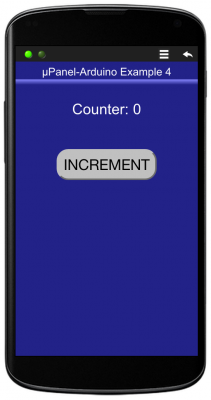
4. Push Counter
In this example a push button will be placed on the Panel. Arduino will count how many times the user pushes the button. The counter value will be shown on the Panel above the button.
Hardware
- TOP03 Arduino Compatible Wi-Fi Board
- Power supply (for example a 5V smartphone charger with micro-USB jack)
µPanel definition
The panel definition includes a text for the panel title, a Message to display the counter value and a push Button.
D!228;T*15:μPanel-Arduino Example 4;{%100,3!88F,228}*20/T:Counter:;&M1:0;//B1p20r40:INCREMENT;
TOP03 Code (Arduino Lilypad USB)
/**************************************************
 --- IMPORTANT ---: before to load your sketch, please select the board "LilyPad Arduino USB" in the boards menu.
 If you have accidentally select another board, and load your sketch, read here:
 www.arduino.cc/en/Guide/ArduinoLilyPadUSB

 Connection table:

 * ESP8266  Arduino
 * GPIO0    12
 * ENABLE   13
 * RX       TX
 * TX       RX
 * GND      GND

 About Serial
 The "Lilypad USB" (and T) use "Serial1" to communicate via TTL serial on pins 0 (RX) and 1 (TX).
 "Serial" is reserved for USB CDC communication.

***************************************************/

#define ESP_PROGRAM_PIN  12
#define ESP_ENABLE_PIN  13

void setup() {

 Serial1.begin(57600);        // Initialise serial 1 (WiFi Module)

  pinMode(ESP_ENABLE_PIN, OUTPUT);
  pinMode(ESP_PROGRAM_PIN, OUTPUT);

  // Set ESP module in RUN mode on reset
  digitalWrite(ESP_PROGRAM_PIN, HIGH);
  digitalWrite(ESP_ENABLE_PIN, HIGH);

  delay(5000);                 // Let's the module start

  // Discharge old partial messages and activate real-time response
  Serial.println("\n$PING 200");

  // Send Panel (a Message and a Button) (sent in two strings just for convenience)
  Serial1.print("$P:D!228;T*15:μPanel-Arduino Example 4;{%100,3!88F,228}");
  Serial1.println("*20/T:Counter:;&M1:0;//B1p20r40:INCREMENT;}");
}

String Msg;
int n = 0;                                             // Create the counter variable

void loop() {

  int c;
  while ((c = Serial1.read()) > '\n') Msg += (char) c;  // Read incoming chars, if any, until new line
  if (c == '\n')                                       // is message complete?
  {
    if (Msg.equals("#B1P"))                            // has Button 1 been pushed?
      {
        Serial1.print("#M1");                           // Update message 1 text:
        Serial1.println(++n,DEC);                       // increment and send the counter value
      }
    Msg = "";
  }
}