Firmware Upload
This page explains how to get the µPanel firmware and to load it into a generic ESP-xx Wi-Fi module. In this way, you can transform your own ESP8266-based Wi-Fi module into a genuine µPanel module.
The firmware that SCF Electronics will provide to you is valid for a single module, thus, in order to receive a valid µPanel firmware (a file *.bin) you have to communicate us the ID of your module.
The following instructions show you how to find out the ID of your module and how to upload the µPanel firmware.
Preliminary check
Your ESP module has to mount a memory with size of at least 8Mbit = 1MB (e.g. memory code 25Q80). A smaller memory is NOT suitable to load the µPanel firmware. Please note that, executing the following steps the firmware currently stored in your module’s memory will be deleted.
Step 1
Connect your ESP-xx board to a USB-TTL serial converter as follow:
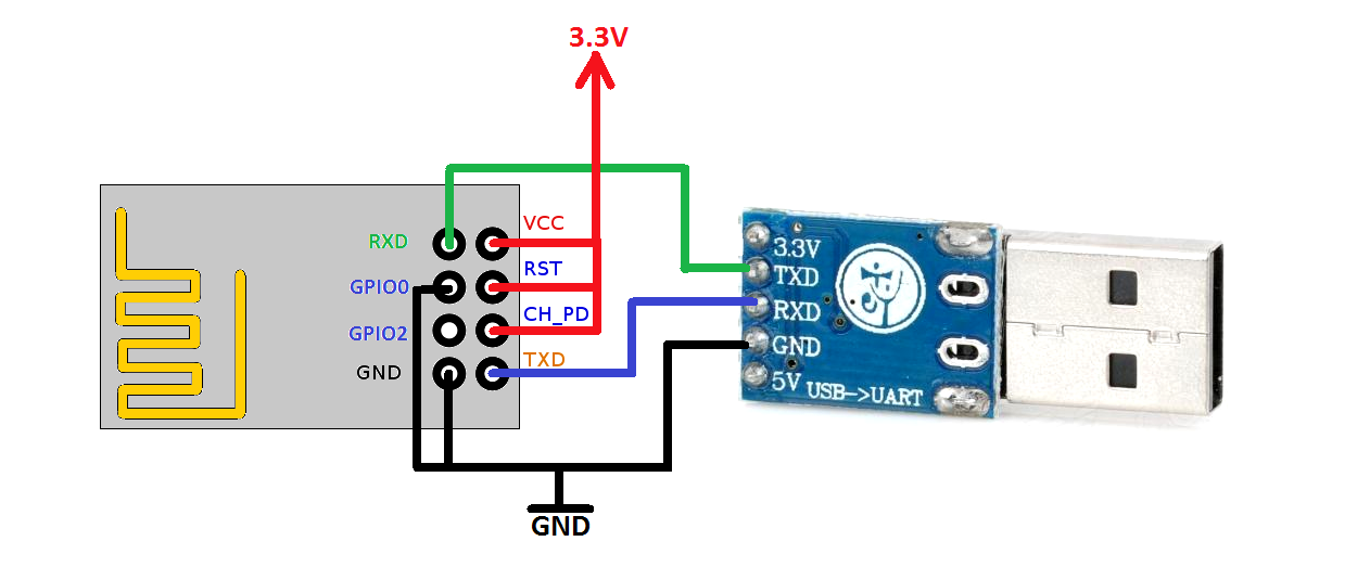
Figure 1. Wiring diagram to program the ESP-01
There are a lot of USB-TTL serial converters, we tested the converter based on Silicon Labs CP2102 chip and the FT232 chip.
Since the Wi-Fi module can boot in different working modalities, to enter the “programming mode” after a reset, its pins should be forced as follow:
– GPIO0 = ‘0’
– GPIO2 = ‘1’
– GPIO15 = ‘0’ (if present)
– CH_PD = ‘1’
– RST = ‘1’
As the ESP-xx board requires more than 200 mA of current, which usually cannot be sourced from a USB-TTL module, you should use an external 3.3 V power source (e.g. 5V, 1A power source followed by a 3.3 V linear voltage regulator like the 1117-3.3 V).
Please note that the GND signal is common for all the components (i.e for ESP, USB-TTL and the external voltage regulator).
Step 2
To serially load the firmware in the module there are a lot of different programming tools available on the Internet. We used the Espressif’s official “esp8266_flasher.exe” program.
– Download into your PC this zipped folder
– Unzip the folder and open it. You will see two files
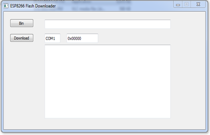
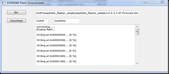
Double click on “esp8266_flasher.exe”. The programming interface will be open:
Click on the BIN button and browse the location of the folder and select the file “bulk_100000000_ID0005.bin“. This firmware will permit you to find out the ID of your module (that you have to communicate to the µPanel team). It is not yet your µPanel firmware!
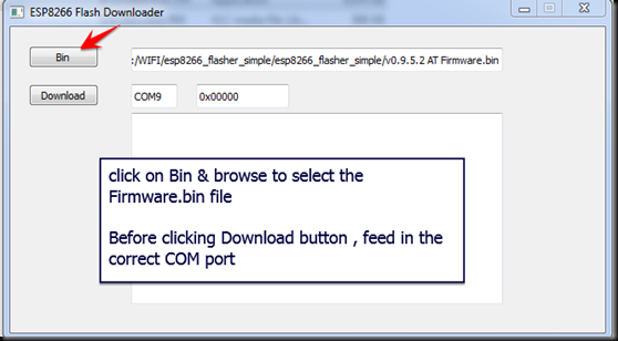
Change the COM port number to that of the USB-TTL converter connected to the PC. The default address 0x000000 is automatically displayed after COM port
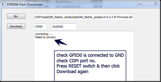
Click the DOWNLOAD button. If you get the “failed to connect” error, your module is not in “programming mode” (maybe you have connected GPIO0 to GND after power ON the ESP board. Switch OFF and ON the power to fix it, and click again the DOWNLOAD button).
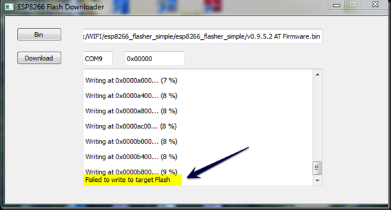
If you get the “Failed to write to target Flash” message as in the screenshot below, add a 100 uF capacitor between VCC and GND to fix it.
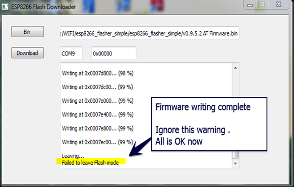
Wait for the flashing process to complete. The STATUS BLUE LED blinks fast while the uploading is going on. A “Failed to leave Flash mode” message after 99% writing, does not affect the flashing process in any way and can be ignored.
Step 3
Turn OFF and ON the WiFi module in “RUN firmware” mode.
To boot in “RUN mode” the ESP8266 pins should be forced as follow:
– GPIO0 = ‘1’
– GPIO2 = ‘1’
– GPIO15 = ‘0’ (if present)
– CH_PD = ‘1’
– RST = ‘1’
The module should now create a WiFi access point whose name contains the ID of your module.
Is something like “ID_xxxxxxxx_yyyyyyyy”.
Step 4
Send us an e-mail to support@miupanel.com containing the following info:
1. The module ID (the code ID_xxxxxxx,yyyyyyy) that you have found in step 3.
2. The payment transaction code of your µPanel firmware
Step 5
When you will receive you µPanel firmware (a .bin file) just repeat the procedure of the Step 2 with the received file to flash the code into your module. Once in “Run mode” your module will create a WiFi access point named “miuPanel_xxxxxxxx_yyyyyyyy”.
You are ready to do great things!