Utility
Control the module’s pins
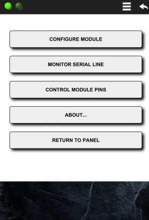
If you need just a pair of controllable digital lines and you aren’t planning to use a micro-controller, you may use the WiFi Module’s pins. In this case you have just to configure the module through the App interface. From the main menu, select the Control Module Pins item:
A sub-menu will appear as follow:
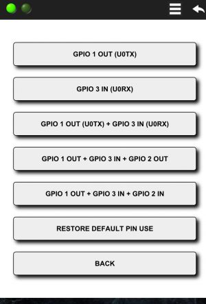
Selecting one of the available choices a predefined panel will be loaded into the µPanel, allowing you to control up to 3 module’s digital lines:
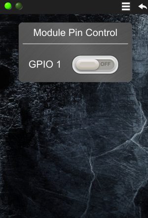
- GPIO 1 OUT (U0TX): selecting this item, the module GPIO 1 pin will be connected to a virtual switch on the µPanel window. Acting on this switch it is possible to control the digital value to emit on the pin. Please note that the GPIO 1 is multiplexed with the serial TX line, thus, during the direct control the serial TX line will not be available. It is still possibile, however, to check the messages through the serial line monitor. The following picture shows the panel that will appear to control the pin:
- GPIO 3 IN: selecting this item, the module GPIO 3 pin will be connected to a virtual indicator (LED) on the µPanel window. Through this indicator it is possible to monitor the digital value of the pin (ON for 1 or high, OFF for 0 or low). Please note that the GPIO 3 is multiplexed with the serial RX line, thus, during the direct monitoring of the pin, it won’t be possibile to send messages to the module through the serial port.
- GPIO 1 OUT + GPIO 3 IN: this item permits to have simultaneously the first pin available for output and the second one for input
- GPIO 1 OUT + GPIO 3 IN + GPIO 2 OUT: selecting this item, with respect to the previous combination, the GPIO 2 pin will be configured as output
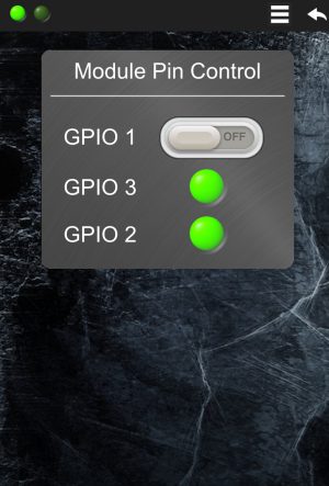
- GPIO 1 OUT + GPIO 3 IN + GPIO 2 IN: this choice permits to have 1 output line and 2 input lines. For this selection, the panel will appear as follow:
Currently, it is not possible to customise the panels for module’s pin control.
Enable the serial line monitor
Either if you are just configuring the module with your App, or designing a new µPanel for your micro-controller based system, it may be very useful to check the messages the module sends out on its serial line. The µPanel firmware allows you to easily monitor directly on your mobile device all the transmitted messages. To activate this monitor, open the App main menu and click on the Monitor Serial Line item, as follow:
A semi-transparent overlay will appear on the Panel window showing the last messages sent by the module on its serial interface

To disable the serial monitor, click again on the same menu entry. Please refer to the module command section for the full list of messages that can transit on the serial line.