System Overview
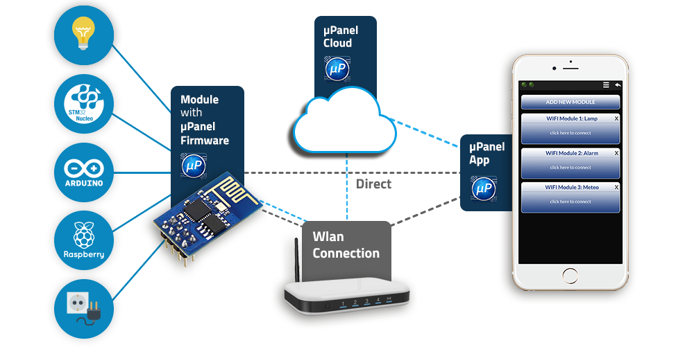
The µPanel system consists of a programmed WiFi radio (µPanel WiFi module), a free mobile App (µPanel App) and an optional and free Cloud server. All these three elements allow the user to control any electronic device connected to the µPanel WiFi module, either locally or through Internet, by means of smartphones and tablets. The uPanel WiFi modules can work with all electronic devices equipped with a serial port, such as Arduino boards, Raspberry boards, or any other microcontroller-based device.
The µPanel APP basically shows the graphical panel (i.e. virtual APP) that is sent by the electronic device through its serial port and allows the user to interact with it. Thanks to a new graphical language (HCTML), the virtual App is completely defined by the electonic device (e.g. Arduino) through a short text line, without requiring the use of libraries or particular resources. The µPanel system is ideal for makers working on very small devices with limited amount of memory, but also for companies that want to quickly add a graphical remote control to already existing products.
In other words µPanel permits to add a fully customised graphical interface (virtual App) to any electronic devices, without the need of programming the mobile APP and without the need of knowing any wireless communication protocol. Nevertheless, the panel that will appear on the smartphone is fully customizable! The designer of the electronic systems can completely define the structure and layout of the panel, including indicators, controls and all other elements required to monitor and control the electronic system in the most efficient way. In addition, it is possible to implement custom and complex IoT solutions, thanks to powerful functions that can access TCP/UDP sockets and thanks to an integrated File system and File transfer.
What can you do with µPanel system?
You can implement your own IoT system in just 10 min!
Build your App
Create a fully customised APP (Android and iOS) to monitor and control your device (locally and through Internet)
Build an Ecosystem
Create a network of devices.
Move your Data
Transfer data and files from your system with Internet
Inside Storage
Store data and file into the µPanel device.
Wireless
Connect your system to Internet wirelessly.
WiFi Connectivity
Add WiFi connectivity to any digital system (even to the smallest micro-controller)
And much more …
The graphical HCTML language has been specifically conceived by the µPanel engineers, so that the graphical and functional aspects of the panel can be handled by the micro-controller consuming a very limited amount of memory. Thus our solution is suitable for any kind of micro-controller, even for the smallest one.
As an example, the designer can easily include LEDs, displays, buttons, switches, sliders, keypads, messages, editable boxes, but also pictures, icons, plots and much more. Moreover, the graphical panel is not static, but it can be even completely changed during the run-time, giving the possibility to implement menus and even true multi-page applications. µPanel will also take care of keeping the panel synchronised with the electronic device, which means the micro-controller doesn’t have to worry about data synchronisation, retransmissions and so on… When the user launches the APP, the current state of controls and indicators will appear automatically! Read on and you will discover as easy it is to use µPanel!
Basic features (FREE):
| Design your own virtual APP in 10 minutes (no need to write any program) | |
| Graphics fully customizable (the Panel design Simulator will help you to design your panel) | |
| Wide collection of Panel Objects (leds, switches, analog controls, plots, images and much more) | |
| NEW – Four connection modes: Direct (access point), Local (through router), Internet (direct), Internet via Cloud-Bridge (no public IP nor router configuration needed). |
|
| NEW – Multiple Apps can simultaneously connect to the device (Cloud-bridge mode only). | |
| NEW – Push notifications (modules can send push notifications, e.g. alarms or other messages). | |
| Data automatically synchronised (e.g. no need to manage retransmissions, logon, logoff,…) | |
| Real-time capability | |
| File System (DISK) for data storage inside the module flash memory (160 KB available) | |
| TCP sockets (both low and high level access. E.g. HTTP file transfer with a single command) | |
| UDP sockets (both low and high level access. E.g. for implementing networks of devices) | |
| No need to learn any programming language | |
| Can be used with any micro-controller through USART (Atmel, Microchip, ST, …) | |
| Design syntax extremely compact (ideal for systems with limited memory) | |
| Easily integrable into pre-existing electronic systems | |
| The µPanel APP it’s FREE and there are NO subscriptions |
NEW – PRO features (subscription):
| Custom images and logos (added to the gallery and usable with all objects, e.g. buttons, backgrounds…) | |
| Dedicated Cloud-Bridge server with guaranteed band and real-time communication capability | |
| Controllable band use with cloud-bridge connection mode | |
| Executable code to set-up and run your own Cloud-bridge server (Linux) |
How µPanel works
Our system consists of three elements:
– a mobile APP installed on a smartphone
– a WiFi module programmed with µPanel connected to the system to be monitored and controlled
– an optional Cloud-bridge server that can act as a bridge to establish the link between App and WiFi module
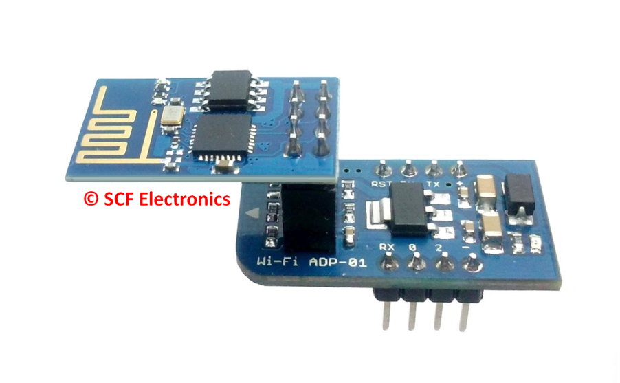 |
Figure 2. Logo of the µPanel App and Wi-Fi module (with its breadboard adapter)
The microcontroller of the system to be controlled communicates with the WiFi module through a common 2-line serial interface and by using a very easy and compact language (HCTML) that has been specifically designed for µPanel.
By means of this language, the microcontroller can easily define both the graphical and functional aspects of the Panel. Moreover, it can both change the Panel state and receive notification messages reporting the user interaction with the panel. No specific knowledge of internet protocols nor of graphical languages are required to successfully use µPanel.
Lets consider a simple example where the electronic system wants to create a panel with a single LED indicator and a push button. In this scenario the microcontroller will initially send through its serial interface the graphical description of the panel, which contains the LED and button definition (you will learn that this message is something like: $P:L1G:0;B1:Push;). Later, when the system wants to turn on/off the remote LED, it will send another simple message through its serial line (something like #L11 for turning on, and #L10 for turning off).
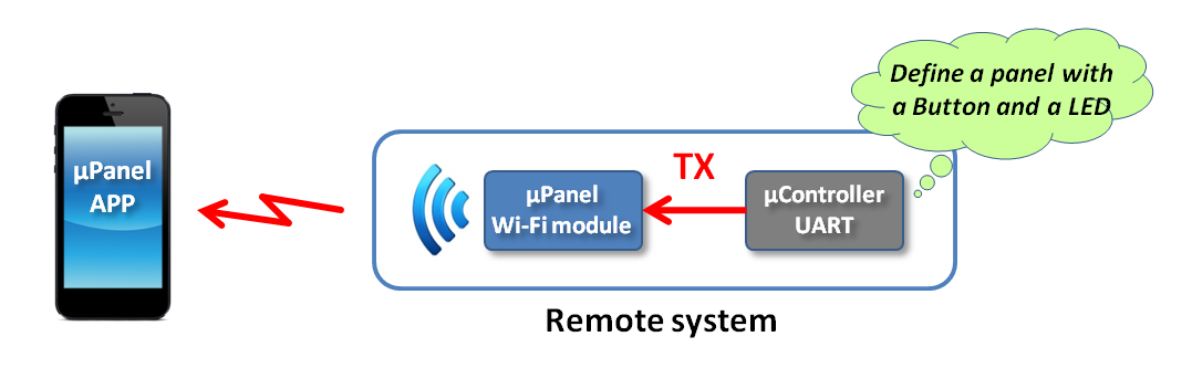
Figure 3. First step: panel layout definition
The WiFi module receives these messages and deliver them to the APP when possible. If the APP is not running at that time, the module will keep them into its memory until the user connects the APP. This way the microcontroller has not to bother about the fact that the user is actually online or not. Everything is synchronised automatically without the intervention of the microcontroller.
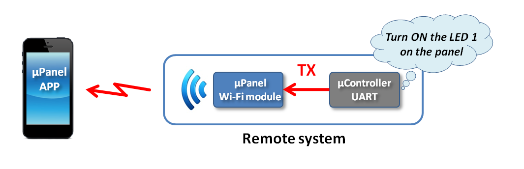
Figure 4. Example of message from your microcontroller to µPanel APP
When the user launches the APP the LED and then button will appear on the screen. The LED will appear on or off, accordingly to the last message sent by the microcontroller. The user can also interact with the button. When the button is pressed, a message will be sent by the APP to the WiFi module, which finally will send a simple HCTML message to the microcontroller reporting the user action (in this example, something like #B1P).
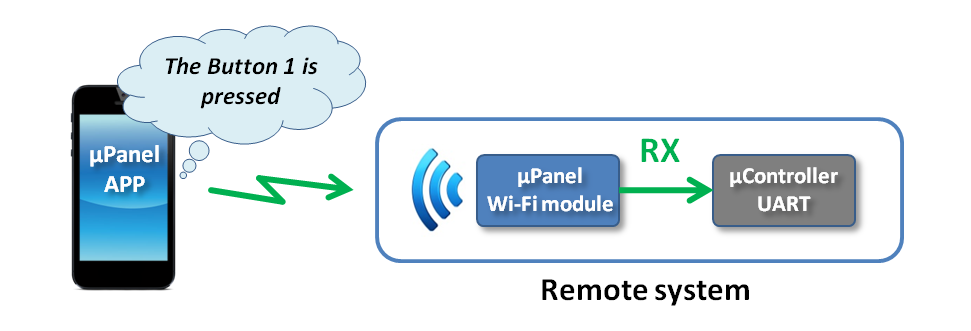
Figure 5. Example of message from µPanel APP to your µController
Connection modes
The µPanel APP can establish a connection with the WiFi module in four ways:
- Direct connection (to the access point of the µPanel module)
- Connection through the LAN
- Connection via INTERNET
- Connection via INTERNET through the Cloud-bridge server
The µPanel APP is developed to automatically search for the selected WiFi module trying, in the order, all the four possibilities.
In the first scenario, your smartphone will connect directly to the WiFi module (seen as an acces point). The connection can be open or protected by a password.
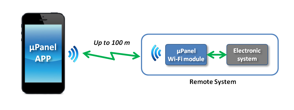
Figure 6. Connection mode 1: Direct connection.
In the second connection mode, both the WiFi module and the mobile device connect to a wireless router (e.g. the home internet router)
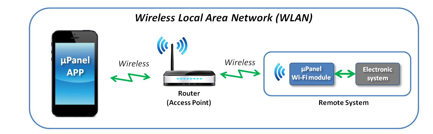
Figure 7. Connection mode 2: through WLAN.
In the third connection mode, the WiFi module connects to a WiFi router that provides Internet connectivity. The mobile device can communicate with the system through its Internet connection.
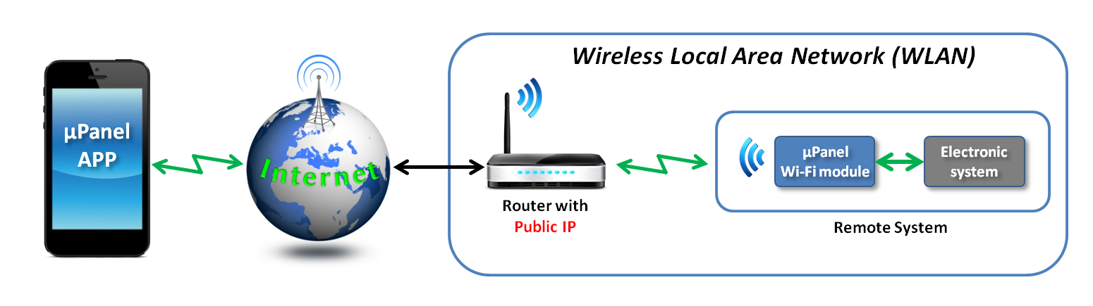
Figure 8. Connection mode 3: through INTERNET.
This connection mode permits to monitor and control your device from everywhere be means of a direct communication between your smartphone and the module. However, this connection mode requires a router with assigned public IP and with port-forwarding capability (some router’s ports have to be configured in order to redirect incoming data to the module ports). This issues are overcome in the fourth connection mode.
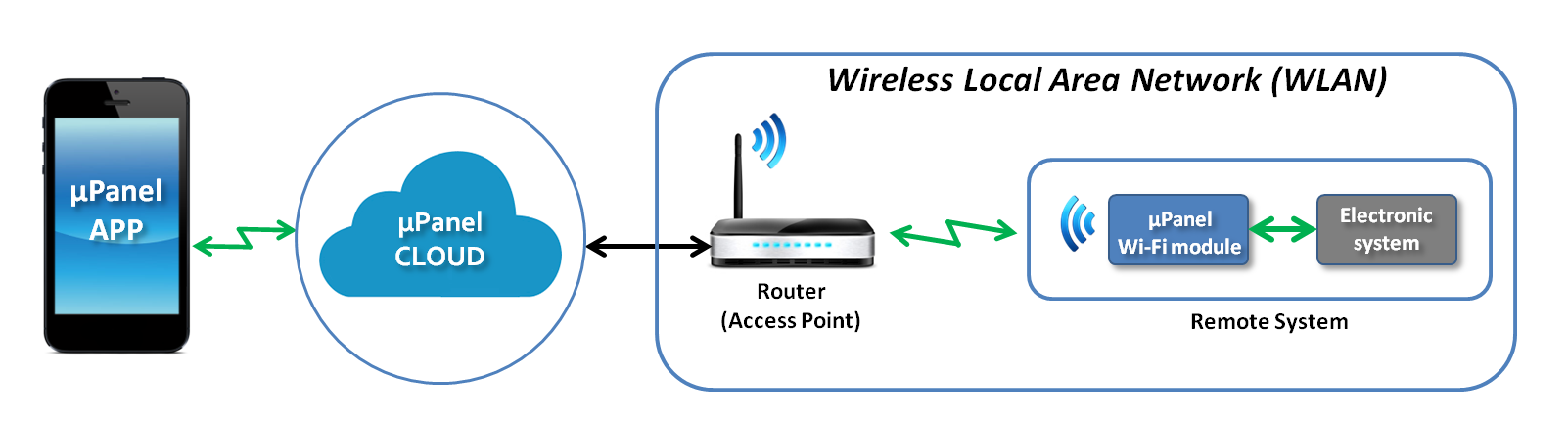
Figure 9. Connection mode 4: through µPanel CLOUD
The fourth connection mode includes a cloud-bridge server that acts as a bridge between the smart-phone and the module and permits them to communicate even if the module can not use a public IP. In addition no router configuration is required. This connection mode is ideal for commercial products since it does not require any action by the final user on the router. On request, we can redirect all the modules of your specific project to a dedicated and exclusive cloud-bridge server in order to guarantee band and real-time performance.