SCF-TOP03
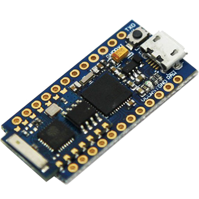
SCF Electronics has adopted this very compact hardware (the Cactus rev.2) with the purpose to develop the TOP on the market of the stand alone Internet-Of-Things (IoT) board.
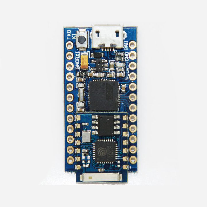
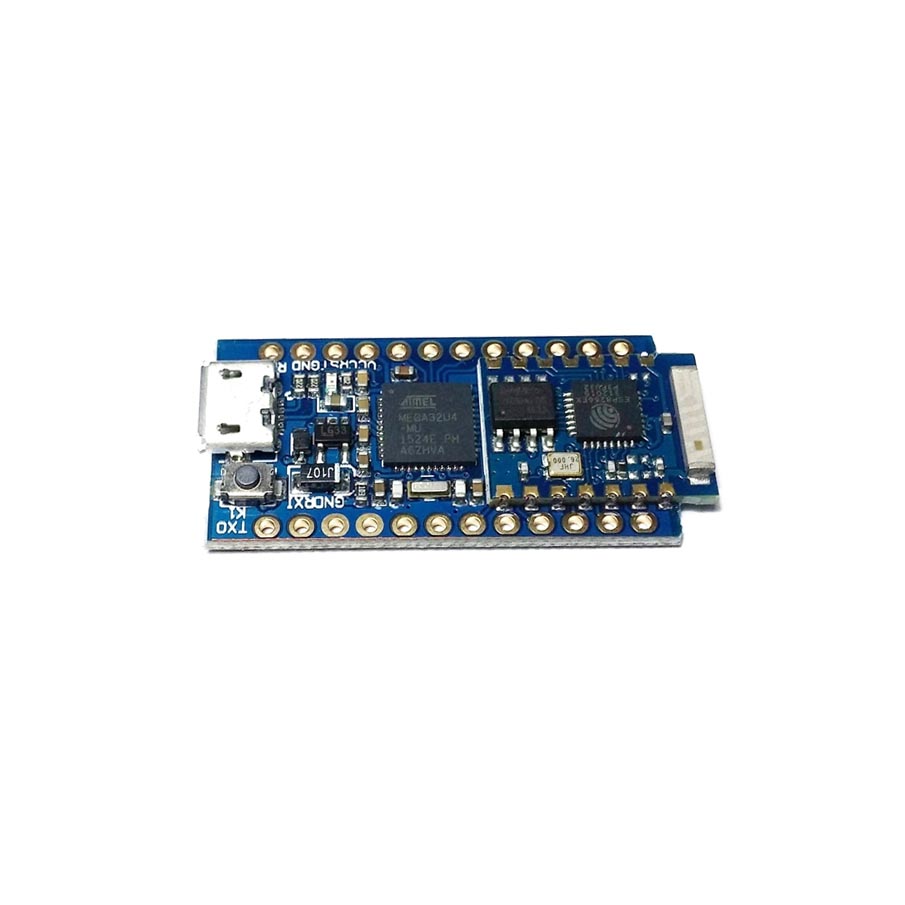
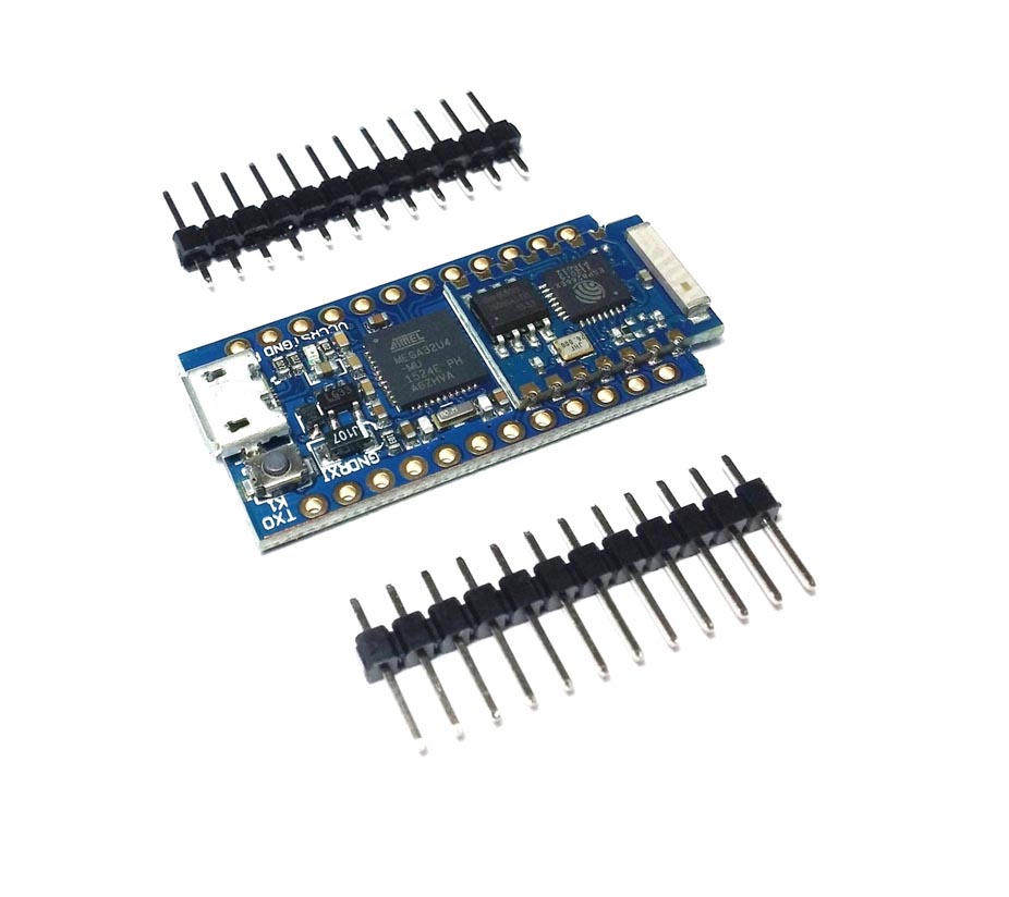
A single board embeds a 100% Arduino compatible board along with a WiFi module. It is a landmark for the makers who want to develop low power IoT projects quickly and easily. The micro-controller unit is the Atmel ATmega32U4 while the WiFi module is based on the ESP8266. To highlight that the WiFi module firmware has been completely changed with respect the other boards in the market, we chose to name it SCF-TOP03.


All the functions of the WiFi Module are managed by the powerful system on chip (SoC) ESP8266, that combines a 32 bit micro-controller (and many peripherals, such as GPIO, I2C, ADC, SPI, PWM) with a WiFi radio.
In the SCF-TOP03 board, the WiFi module pins are internally connected to the Arduino’s pins as follow:
| ESP8266 | Arduino |
|---|---|
| GPIO0 | 12 |
| ENABLE (CH_PD) | 13 |
| RX | TX (Serial1) |
| TX | RX (Serial1) |
| GND | GND |
| GPIO13 | 2 |
| GPIO12 | 3 |
| GPIO14 | A4 |
* Not managed from miuPanel firmware.
Power Pins
There are a variety of power and power-related nets broken out:
RAW is the unregulated voltage input. If the board is powered via USB, the voltage at this pin will be about 4.8V (USB’s 5V minus a schottky diode drop). On the other hand, if the board is powered externally, through this pin, the applied voltage can be up to 9V.
VCC is the voltage supplied to the on-board ATmega32U4. It’ll be 3.3V. This voltage is regulated by the voltage applied to the RAW pin. If the board is powered through the ‘RAW’ pin (or USB), this pin can be used as an output to supply other devices.
RST can be used to restart the ATmega32U4. This pin is pulled high by a 10 kOhm resistor on the board, and is active-low, so it must be connected to ground to initiate a reset. The ATmega32U4 will remain “off” until the reset line is pulled back to high.
GND, is the common, ground voltage (0V reference) for the system.
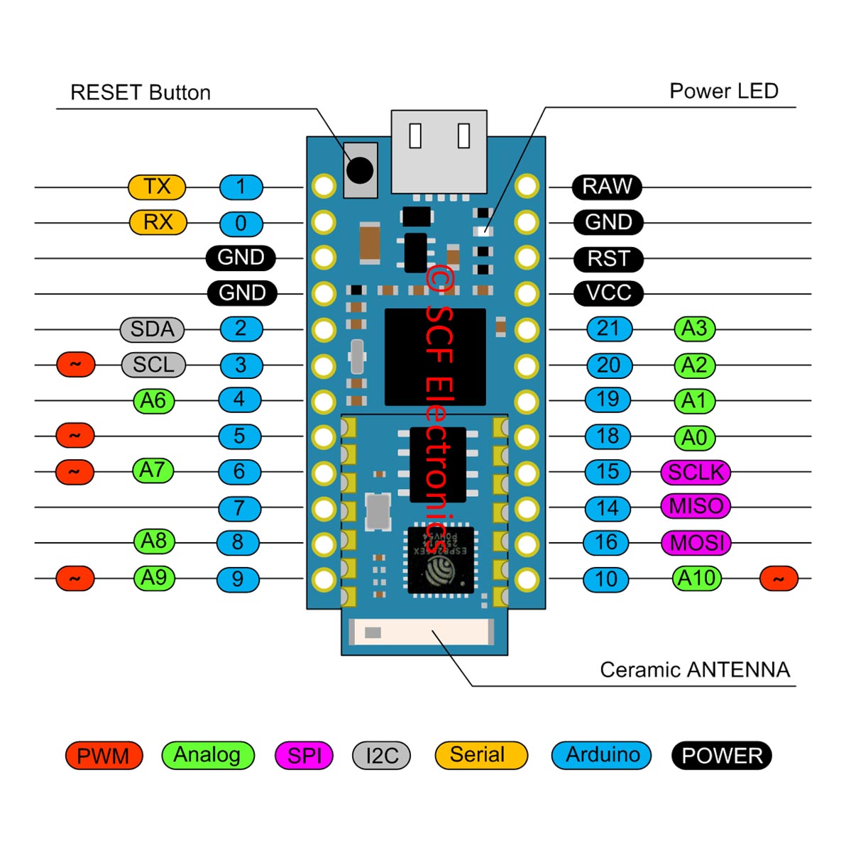
I/O Pins
The board’s I/O pins – 18 in all – are multi-talented. Every pin can be used as a digital input or output, for blinking LEDs or reading button presses. These pins are referenced in the Arduino IDE via an integer value between 0 and 21. (The A0-A3 pins can be referenced digitally using either their analog or digital pin number).
Nine pins feature analog to digital converters (ADCs) and can be used as analog inputs. These are useful for reading potentiometers or other analog devices using the analogRead([pin]) function.
There are five pins with pulse width modulation (PWM) functionality, which can be used as analog output using the analogWrite([pin], [value]) function. These pins are indicated on-board with a faint, white circle around them.
There are hardware UART (serial), I2C, and SPI pins available as well. These can be used to interface with digital devices like serial LCDs, XBees, IMUs, and other serial sensors.
The board has five external interrupts, which allow you to instantly trigger a function when a pin goes either high or low (or both). If you attach an interrupt to an interrupt-enabled pin, you’ll need to know the specific interrupt to pin map: pin 3 maps to interrupt 0, pin 2 is interrupt 1, pin 0 is interrupt 2, pin 1 is interrupt 3, and pin 7 is interrupt 4.
How to Power the board
Since the main feature is its innate USB functionality, the most common way to power it is via USB. In this setup, the board will regulate to 3.3V the 5V supply coming in from the USB. The other end of the USB cable can be connected to either a computer, USB hub, or a USB wall adapter, which can (in most cases) provide more power.
Alternatively, if your board is living out in the wild, it can be powered through either the ‘RAW’ or ‘VCC’ pins. A supply going into the ‘RAW’ pin will be regulated down to the correct operating voltage (3.3V). To be safe, it shouldn’t be any higher than 9V, and it should be at least 1V more than the regulated voltage (e.g. > 4.3V).
If you power the board through the ‘VCC’ pin, keep in mind that this signal is unregulated. Only use this if you have a clean, regulated 3.3V supply to connect to it.
Operating mode of the onboard WiFi Module
After power-up (or reset) the on-board WiFi module can boot in two different modes, depending on the logic levels applied on its pins GPIO0 and GPIO2. Since these pins are internally routed to the Arduino side (as reported in table 1), in your Arduino sketch you have to take care to correctly set these pins on reset (see the sketch example below).
Arduino Sketch Example
IMPORTANT: before loading your sketch, please select the board “LilyPad Arduino USB” in the boards menu.
If you have accidentally selected another board, and already tried loading your sketch, read here:
www.arduino.cc/en/Guide/ArduinoLilyPadUSB
This board (like Lilypad USB and Leonardo) use “Serial1” to communicate with on-board the WiFi module via TTL serial on pins 0 (RX) and 1 (TX). “Serial” is reserved for USB CDC communication.
/**************************************************

 --- IMPORTANT ---: before to load your sketch, please select the board "LilyPad Arduino USB" in the boards menu.
 If you have accidentally select another board, and load your sketch, read here:
 www.arduino.cc/en/Guide/ArduinoLilyPadUSB

 Connection table:

 * ESP8266  Arduino
 * GPIO0    12
 * ENABLE   13
 * RX       TX
 * TX       RX
 * GND      GND

 About Serial
 The "Lilypad USB" (and the board derived from it) use "Serial1" to communicate via TTL serial on pins 0 (RX) and 1 (TX).
 "Serial" is reserved for USB CDC communication.

 ***************************************************/

#define ESP_PROGRAM_PIN  12
#define ESP_ENABLE_PIN  13

void setup() {

  Serial1.begin(57600);        // Initialise serial 1 (WiFi Module)

  pinMode(ESP_ENABLE_PIN, OUTPUT);
  pinMode(ESP_PROGRAM_PIN, OUTPUT);

  // Set ESP module in RUN mode on reset
  digitalWrite(ESP_PROGRAM_PIN, HIGH);
  digitalWrite(ESP_ENABLE_PIN, HIGH);

  delay(5000);                 // Let's the module start

  // Discharge old partial messages
  Serial1.println("");

  // Enable real-time response
  Serial1.println("$PING 200");

  // Send Panel (Single Green LED, 150% size on new line with text Blinking)
  Serial1.println("$P:*15/L1G:0:Blinking;");

}

void loop() {

  delay(500);                // Wait 0.5 s
  Serial1.println("#L11");    // Turn ON LED 1
  delay(500);                // Wait 0.5 s
  Serial1.println("#L10");    // Turn OFF LED 1

}