Electric wiring
The serial protocol
The communication between the WiFi module and your microcontroller is performed by means of a standard asynchronous serial protocol. Almost all microcontrollers are equipped with at least one Universal Asynchronous Receiver Transmitter interface (UART), thus, the establishment of the communication is usually straightforward.
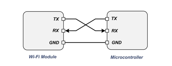
The serial protocol is asynchronous and the bus consists of just two wires, the receiver line, RX, the transmitter line, TX as depicted in the following picture:
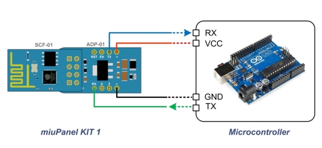
The following figure shows a practical wiring example between the miuPanel kit1 (SCF-01 WiFi module + the level adapter ADP-01) and a development board:
The serial protocol is usually configurable, thus, it is important to make sure that both devices on the serial bus are configured to use the exact same settings. In particular, to communicate with WiFi module the micro-controller’s UART has to be set as follow:
- Data bits: 8
- Stop bits: 1
- Parity bits: 0
- Baud rate: 57600
- Flux control: None
The default baud rate of the Wi-Fi module is 57600 baud, but it can be changed both from APP or through a serial command.
Power Supply
Depending on the employed WiFi module, the power supply and the electrical voltage on the bus, must be as follow:
- SCF-01 or SCF-12 module without adapter: 3.3 V
- SCF-01 module with adapter ADP-01: 5.0 V
Please note that the power supply must be able to provide at least 300 mA
Module Activation
When you receive the WiFi module, you have to activate the product and enable your mobile phone to talk with the module. When the module is powered-up for the first time, the µPanel firmware will run and create a WiFi access point whose name is miuPanel. This access point represents the primary method for setting-up your module.
In order to proceed with the following instructions you will have to install the µPanel App on your mobile device. Launching the App from your smartphone, the screen reported in the following picture should appear, indicating that you are ready to add your new module:

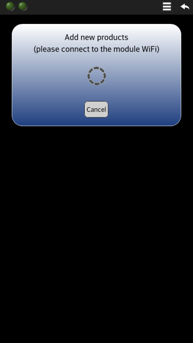
First of all, enable the WiFi of your mobile device and select the miuPanel from the list. Since the WiFi connection is protected, you will be asked for the password. The initial module’s password is uPanel11 (please note that the P is upper case). When connected, press on the Add New Module button. You will see the following message confirming that the App is actually trying to connect to your module

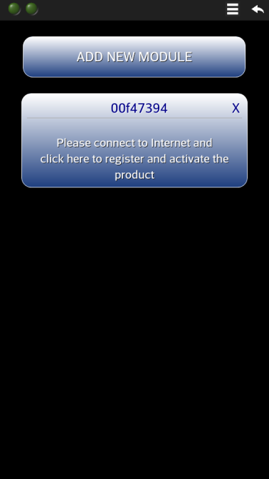
After a while your module should appear in your device’s screen as shown by the following picture. The header of the new product box shows the serial number that identifies your product. If you wish, you can assign a user friendly name to your module simply by clicking on its serial number and entering the name you like.
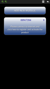
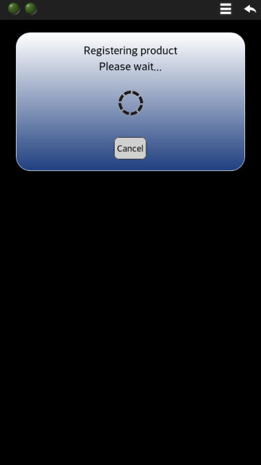
You are just a step away from your Panel! To activate your module, make sure your mobile device is actually connected to the Internet (disconnect your device from the miuPanel WiFi and connect to another WiFi or mobile data network which give an internet access) and click on your product box. The following message will appear:

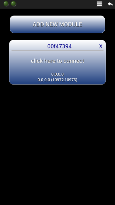
In a while you should see your product with the message “click here to connect“, as shown in the following picture, indicating that your product has been correctly registered and activated.

Now in the bottom part of your module button the App also shows both the module local and public IP. You will find more information about these IP in the Router and Module in the next guide section “module configuration”.
Now press on your module button to connect to your module! Remember that since you have not yet enabled the WiFi module to connect to any router, before press on “click to connect” you have to reconnect your mobile device directly to the miuPanel WiFi Access Point).
NOTE: if the app shows the message “your product can not be regitered!” this simply means that your miupanel vendor has not yet activated the module registration after the sales, so the registration fail. Usually the vendor activates the registration of your wi-fi module whithin 24 hours the sale. In this case, you can contact your vendor to request the activation.
You should obtain the screen reported in the following picture that shows the module has replied indicating that there is not yet a panel to show you. Congratulations! You are now ready to start with your µPanel!

Please note that the first LED (on the left) in the tool bar will stay steady ON, indicating that your mobile device is connected and communicating with the module. The second LED (on the right), instead will flash only when data and commands are successfully transmitted from your mobile device to your module.
Please go to the next section to know how to configure your module
Initial configuration
In this section are described the module’s configurations to set to permit the App to reach your module from remote.
The WiFi module can be configured using either the menu on the App or the module serial interface to send the serial command. In this section we will present the former method.
To better undestand the following configurations, keep in mind that the µPanel APP will search automatically your remote wifi module scanning sequentially four connection mode:
- Direct connection (to the access point of the µPanel module)
- Connection through the WLAN
- Connection via INTERNET (works only if the router has a static public IP)
- Connection via µPanel CLOUD (works with any router, no router configuration are needed!)
The first mode that will permit to reach the remote module will be used from the App. From the users point of view, the connection mode choosed from the app to communicate with the module are irrilevant.
To access to the menu: connect the mobile phone to the WiFi Access Point of the miuPanel module >>> open the App and access to the module (by clicking on “click to connect” button) >>> click on the Menu button, located on the right side of the tool bar, the following menu will appear.
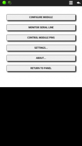
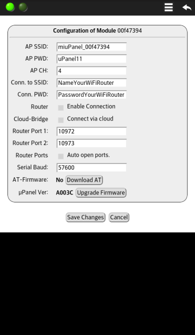
The first menu item (Configure Module) allows you to access the page with the module configuration:

The presented form includes the following basic fields:
- AP SSID: this field represents the name of the Access Point created by the module. Enter a new name if you wish to use another Access Point name
- AP PWD: this is the password of the module Access Point. It is strongly recommended to change the initial password. Please note that the minimum allowed password length is 8 characters. If you leave this field empty, an open Access Point will be created
- AP CH: this is the radio channel used by the Access Point. Despite this parameter is reported in the form, in most of the cases, you won’t be able to change this parameter while the WiFi is in use. It is therefore recommended to change this parameter through the Serial Interface
- Conn. to SSID: enter the name of the local existing WiFi (for instance your home WiFi router) that can be used to connect to Internet. This is usually your Home WiFi network name. Please note that, it is not required that this network is actually connected to the Internet, but it can just connects your local devices
- Conn PWD: enter the password of your WiFi router
- Enable Connection: check this box if you want actually connect the module to your WiFi network. Leave this box unchecked if you don’t wont to connect the module to your WLAN and Internet.
The following configuration are useful to communicate with your module from the Internet (i.e. from everywhere in the world).
- Cloud-Bridge: check the box “connect via Cloud” is all you have to do for enable the cloud connection. Cloud-bridge server acts as a bridge between the smart-phone and the module and permits them to communicate even if the module is connected to a router that has not a static public IP.
If you have a router with static public IP, instead to enable the CLOUD, you can set your router to permit the App to directly reach the module from outside. In order to be able to communicate with your module from the Internet (i.e. from everywhere in the world) you have to configure your router to allow incoming TCP connections to reach the module port 80 and 81. The µPanel firmware is able to automatically configure most of the routers so that they will accept and forward these incoming connections. The currently supported protocols are the NAT-PMP and UPnP. The former is adopted by Apple products, the latter by many home routers. The following three entries of the configuration module permit to set and enable the router auto-configurator function:
- Router Port 1: this field allows you to select a free router public port. The router will be configured to forward incoming TCP connections from this port to the module port 80
- Router Port 2: as above, the router will be configured to forward incoming TCP connections from this port to the module port 81
- Enable Router Conf.: checking this box the router auto-configuration function will be actually activated. Please note that if you activate this function, the module may require about 1 minute to successfully connect to Internet after start-up
The last module entries permit to configure and access the following features:
- Serial Baud: this parameter permits to change the Serial Line speed. The default value is 57600 baud, but other standard values can be set, such as 115200 baud, for faster communication
- AT-Firmware: the module will be shipped with actually two firmwares onboard: the µPanel and the legacy AT. This menu line shows you if the firmware is actually revertible to AT. If you click on Revert to AT the module will switch firmware and will reboot with the AT interpreter. If you revert to AT, the only way to return back to the µPanel firmware is to issue an AT+PANEL command on the serial line (at 115200 baud). More details about the AT reverting procedure can be found in its specific section
- µPanel Ver.: this line shows the firmware version currently running on the module. Clicking on the upgrade button you can upgrade the firmware. The upgrade functions require internet connection. More details about the firmware upgrade can be found in the specific section
Some of the above discussed parameters and functions might be protected and locked by a controller connected to the serial port. Please refer to the serial section to know more about the protected commands.
The best manner to run your first panel is to see the examples.
See the sketchs of some basic examples written for Arduino UNO connected to miuPanel Kit1:
See the sketchs of some basic examples written for the miuPanel board TOP-03 (100% Arduino compatible):