Design Examples
This section reports some step-by-step examples of panel design
1.0 Design a panel with 2 status LEDs and a double 7-segment LCD
Design a panel with 2 status LEDs and a double 7-segment LCD
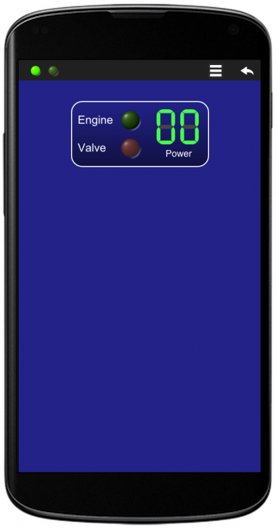
Task: design a panel with two LED indicators, including text on their left-hand side, and with a numeric indicator composed of two 7-segment LCDs. The first led (green) should report the text “Engine”, while the second one (red) should report the text “Valve”. Arrange the two LED indicators on two rows and the 7-segment LCDs next to the LEDs (on the right). Include the text “Power” under the 7-segment LCDs. Set the display background dark-blue.
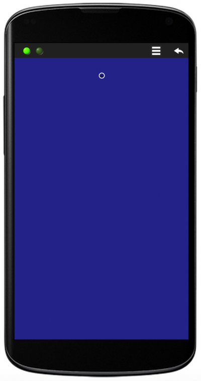
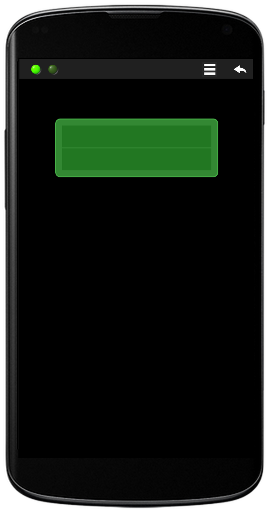
Step 1: Define the display background color (using the Desktop object) and create the panel container with rounded solid border, background with gradient blue, object size slightly larger than the default. Insert two empty face-to-face sub-containers (the first one will contain the LEDs indicators, the second one will contain the 7-segment LCDs)
Panel definition: D!228;/{-r30!228,114*12{}|{}}
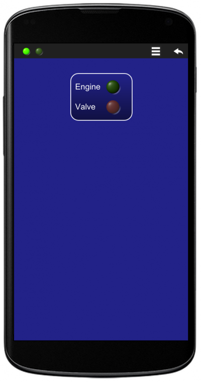
Step 2: Insert the first sub-container content: a 2×2 table with texts on the first column and LEDs on the second column.
Panel definition: D!228;/{-r30!228,114*12{T:Engine;|L1G:0;_T:Valve;|L2R:0;}|{}}
Step 3: Insert the second sub-container content: a 2-row table with the 7-segment LCDs on the first row and the “Power” text on the second row. Align the text content using the center styler (^) on the sub-container. Slightly reduce the size of objects.
Panel definition: D!228;/{-r30!228,114*12{T:Engine;|L1G:0;_T:Valve;|L2R:0;}|{^*8L35:0;&L45:0;_T:Power;}}
2.0 Design a numeric keypad
Design a numeric keypad
Task: design a 4×3 numeric keypad.
Note: since this panel requires the definition of 12 graphically identical keys, in order to keep the panel’s string short, it is convenient to define a styler class (with the S virtual object) and to apply the class to all the keys (with the s styler), instead of repeating the stylers for all the keys.
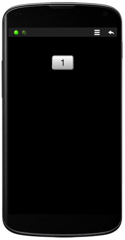
Step 1: Define a style (ID=1) with font-size proportional to the parent container size, container size of 20%, rounded border, gradient background color from white to grey, black box shadow. Try the style with a test button
Style definition: S1*.*20%20r15!FFF,AAAh5,000,15;
Test button with the defined style: /B1s1:1;
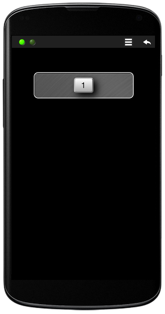
Step 2: Define the keypad container of width 70%, centered content, solid rounded border of 20 eq. pixels, padding 20 eq. pixels, back ground texture number 2. Insert the text button into the container.
Style definition: S1*.*20%20r15!FFF,AAAh5,000,15;
Panel design: /{%70^-p20r20g2|B1s1:1;}
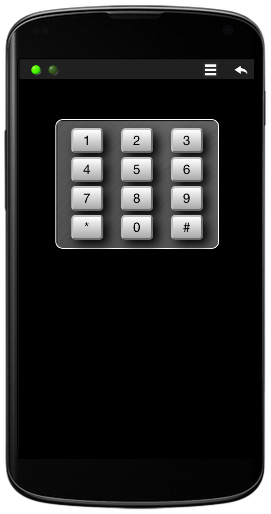
Step 3: Complete the matrix of keys by inserting the other rows and columns into the keypad container
Style definition: S1*.*20%20r15!FFF,AAAh5,000,15;
Panel design: /{%70^-p20r20g2|B1s1:1;|B1s1:2;|B1s1:3;_|B1s1:4;|B1s1:5;|B1s1:6;_|B1s1:7;|B1s1:8;|B1s1:9;_|B1s1:*;|B1s1:0;|B1s1:#;}
3.0 Design a classic 16x2 LCD
Design a classic 16×2 LCD
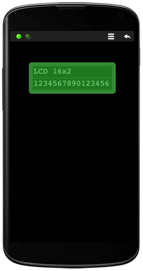
Task: design a classic 16×2 LCD macro with parametric size.
Step 1: Create the LCD container with light green rounded solid border, padding, centered content, dark green background, parametric size and font courier
Macro definition: K1:{r15p10#4A4-^!383%?fc}$
Macro usage: /J1(70)
Step 2: Insert into the LCD frame two rows with collapsed light border, darker green background. Create a cell per row with length that covers the whole LCD area and size ratio of 1/9 (height over length). Left align the cell’s content and set some padding.
Macro definition: K1:{r15p10#4A4-^!383%?,1fc{-c#383!272_-|%99,11+-<p9_-|%99,11+-<p9}}$
Macro usage: /J1(70)
Step 3: Insert into the LCD rows two Message objects. Set the Message’s size proportional to the parent container (LCD Frame), so that each row contains exactly 16 characters, and light green color. Use auto Indexed Messages with parametric content.
Macro definition: K1:{r15p10#4A4-^!383%?,1fc{-c#383!272*.*23_-|%99,11+-<p9M??#8D8:?;_-|%99,11+-<p9M??#8D8:?;}}$
Macro usage: /J1(70,LCD 16×2,1234567890123456)