WiFi Module SCF-01
We chose to use a WiFi hardware already widely employed on the market (the ESP-01) on which we uploaded our innovative µPanel firmware. To highlight the fact the module firmware has been completely changed with respect to other commercial products, we chose to name it SCF-01.


All the functions of the WiFi Module are managed by the powerful system on chip (SoC) ESP8266, that combines a 32 bit micro-controller (and many peripherals, such as GPIO, I2C, ADC, SPI, PWM) with a WiFi radio.
Pins of the SCF-01 module
| GND | Ground |
| TX | UART Transmit pin |
| GPIO2 | General Purpose I/O |
| CHIP_EN | Chip Enable, active high |
| GPIO0 | General Purpose I/O |
| RST | External reset signal, active low |
| RX | UART Receive pin |
| VDD | +3.3V power input |
Leds Module
| LED Red |
(PWR) |
Connected to VCC, steady on when power is applied |
| LED Blue | (TXD) | UART TX indicator, tied in hardware to U0TXD |
Operating mode
After power-up (or reset) the module can boot in two different modes, depending on the logic levels applied on pins GPIO0 and GPIO2:
IMPORTANT: to correctly update the module’s µPanel firmware, do NOT use this solution, otherwise you will lose definitely the µPanel firmware! The correct way is launch the update request from µPanel APP, from the module configuration menu.
Electrical specification
This module requires 3.3V on VCC and 3.3 V for the logic. It does NOT tolerate 5 V!
It is therefore necessary to power it from a 3.3V source with a current capacity of at least 300 mA (in fact, although the average current consumption of the Wi-Fi module is about 100 mA, the module has higher current absorption peaks).
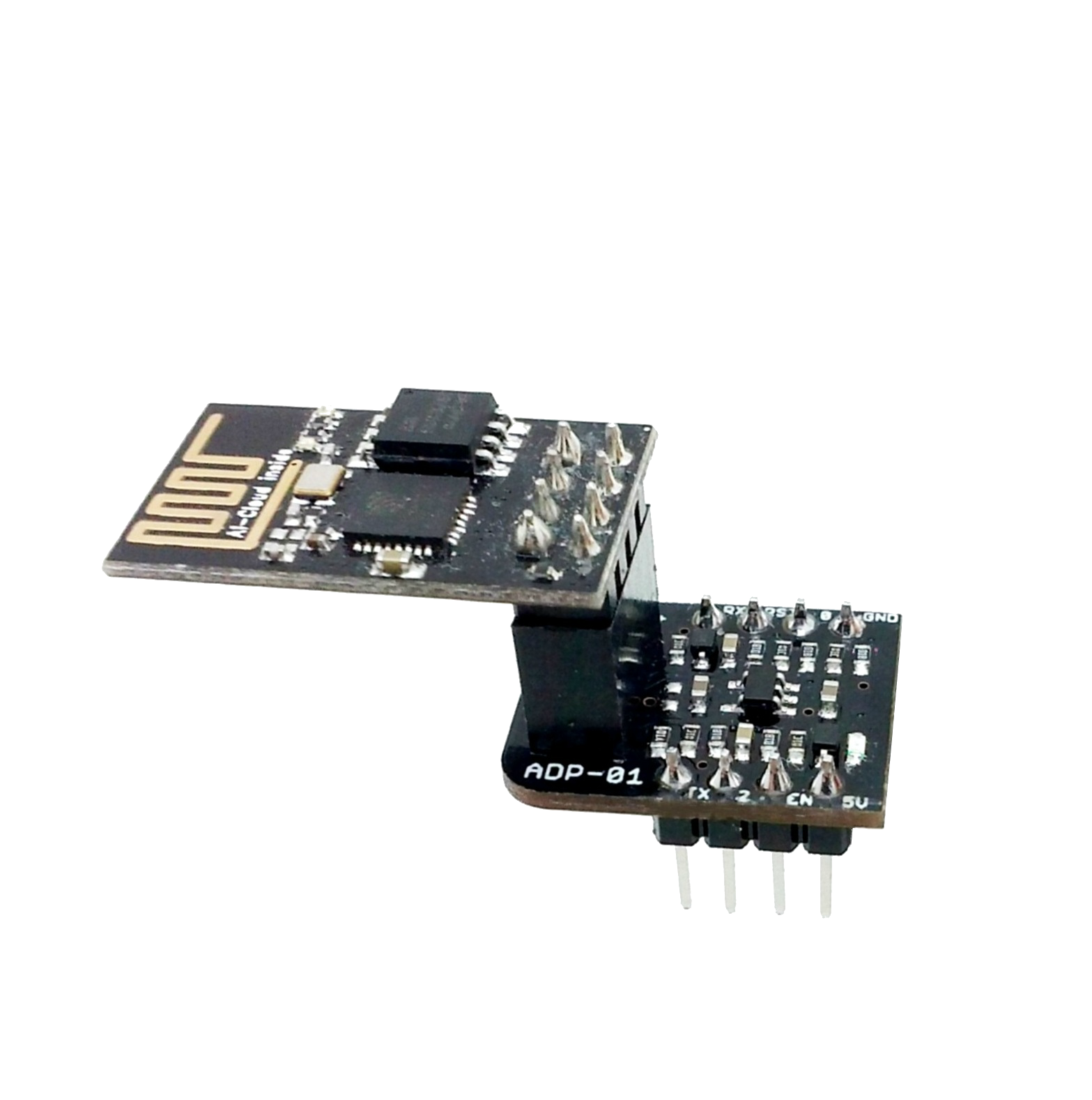
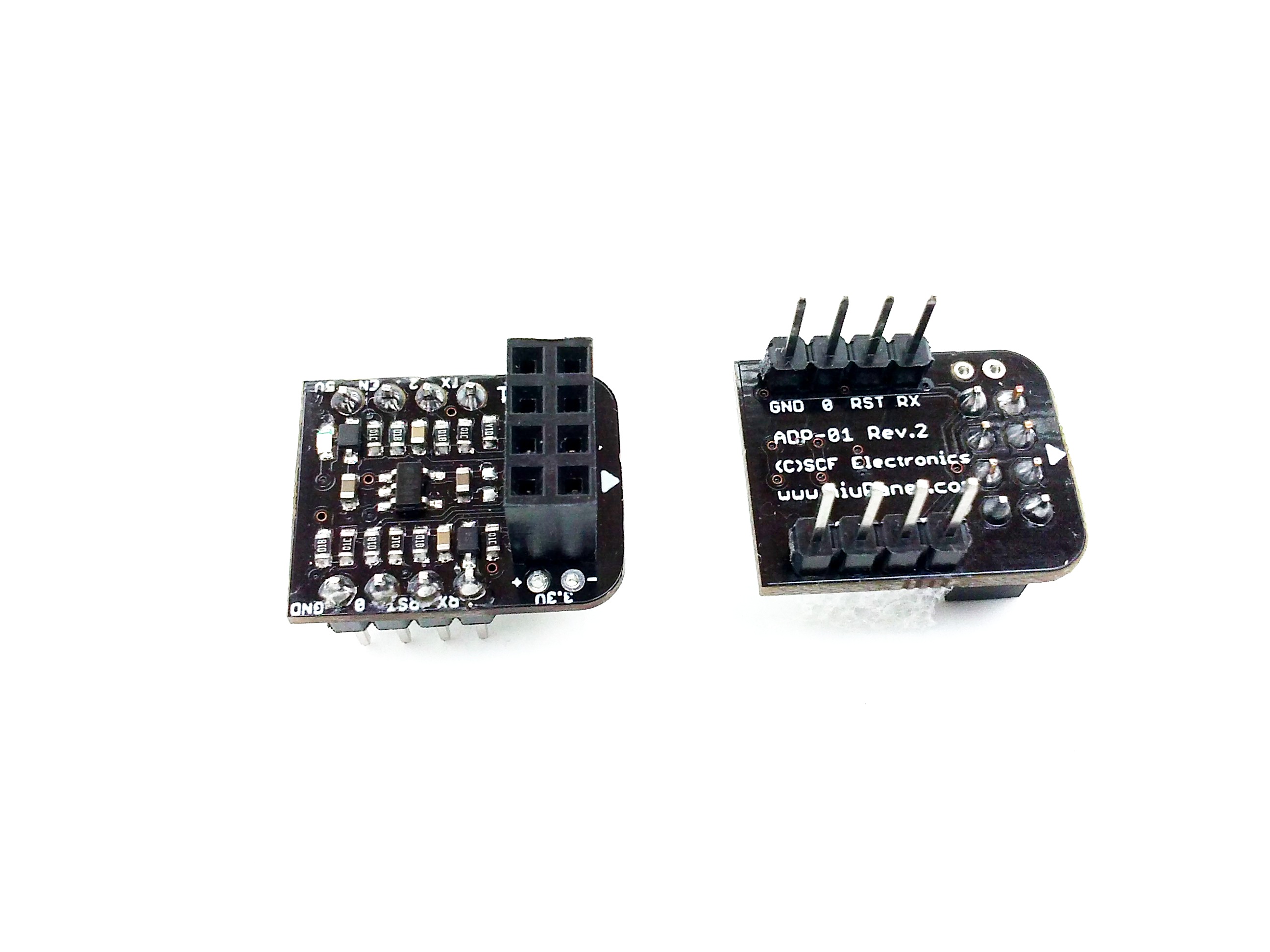
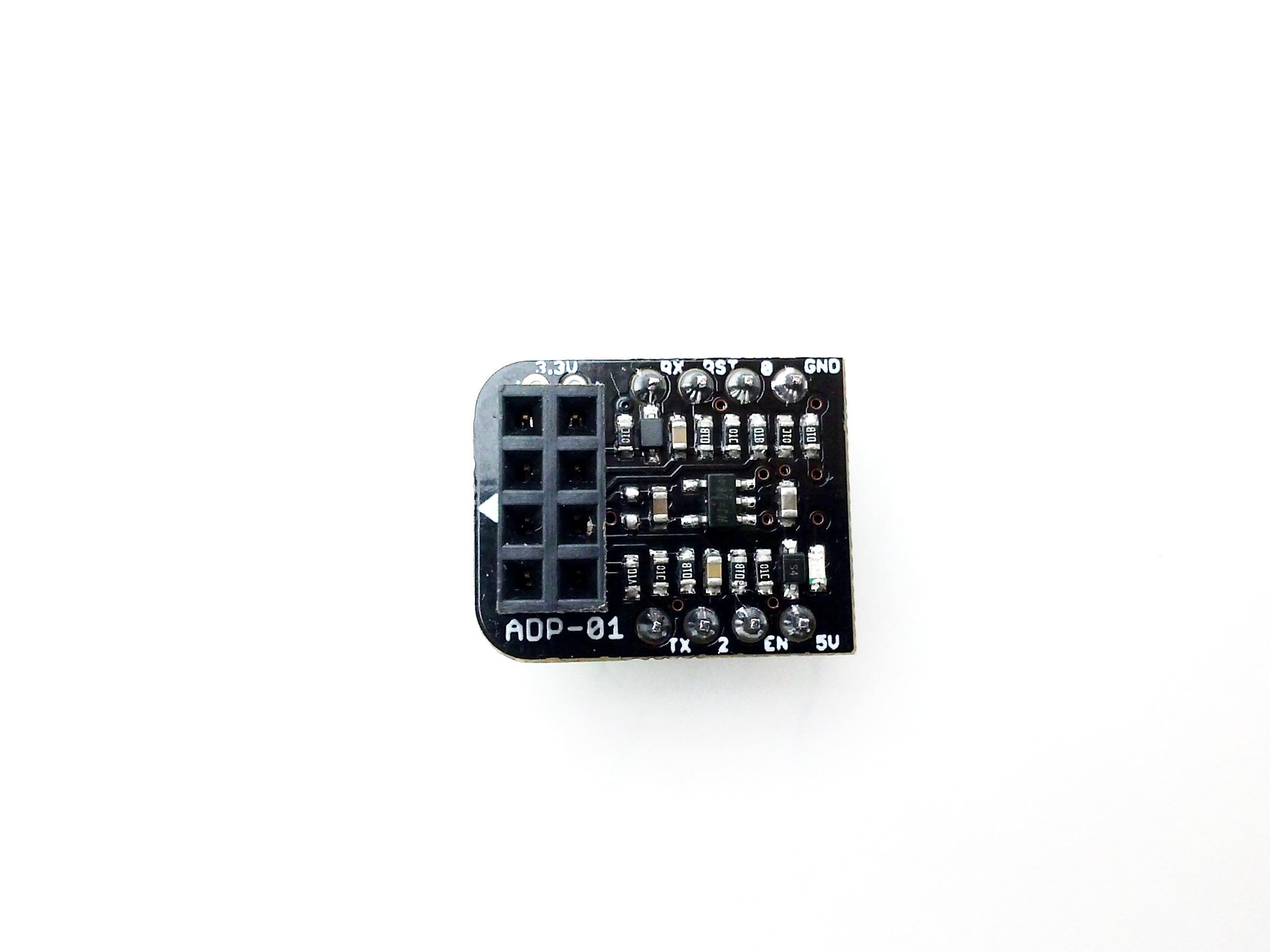
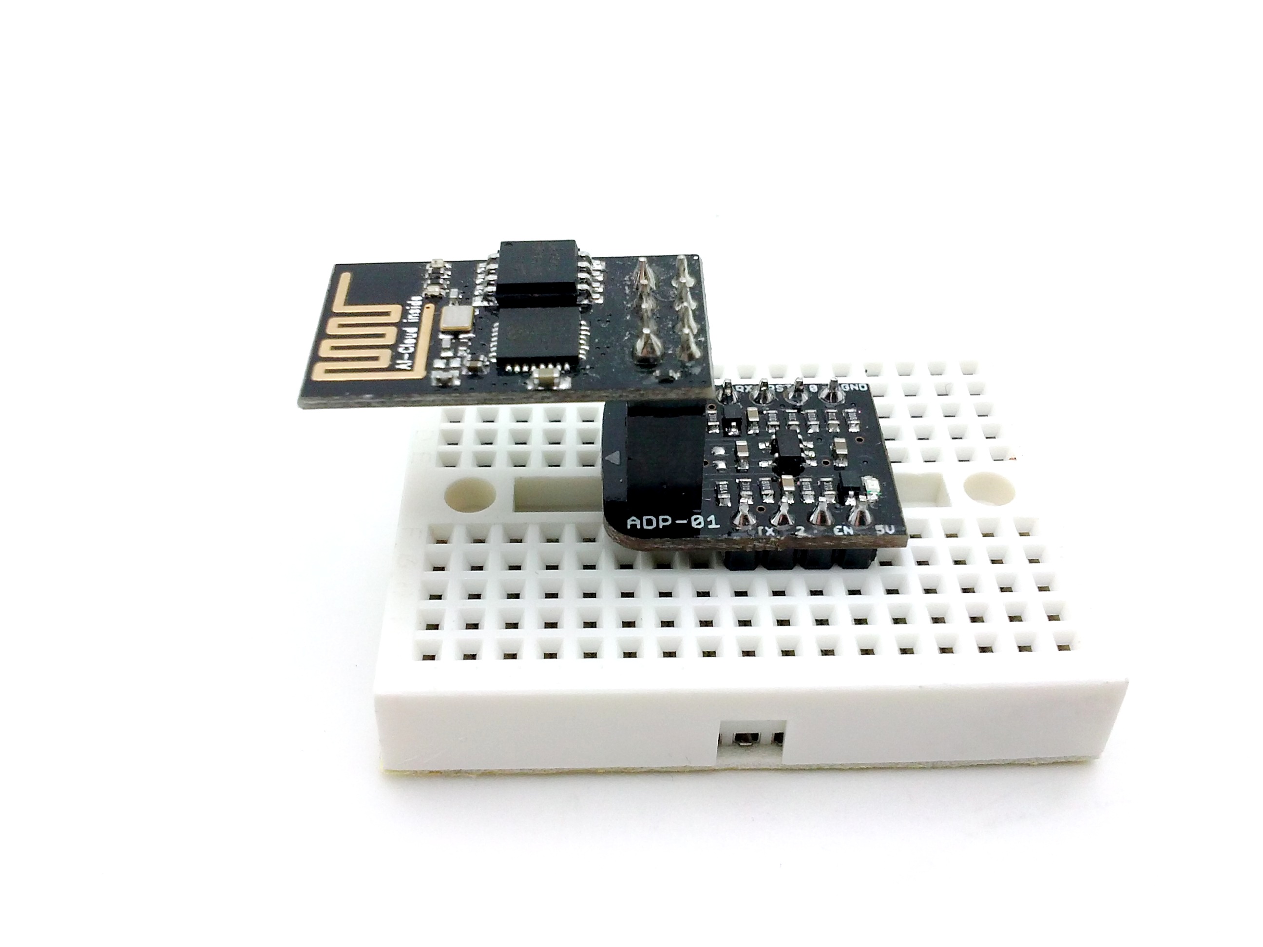
Breadboard adapter ADP-01
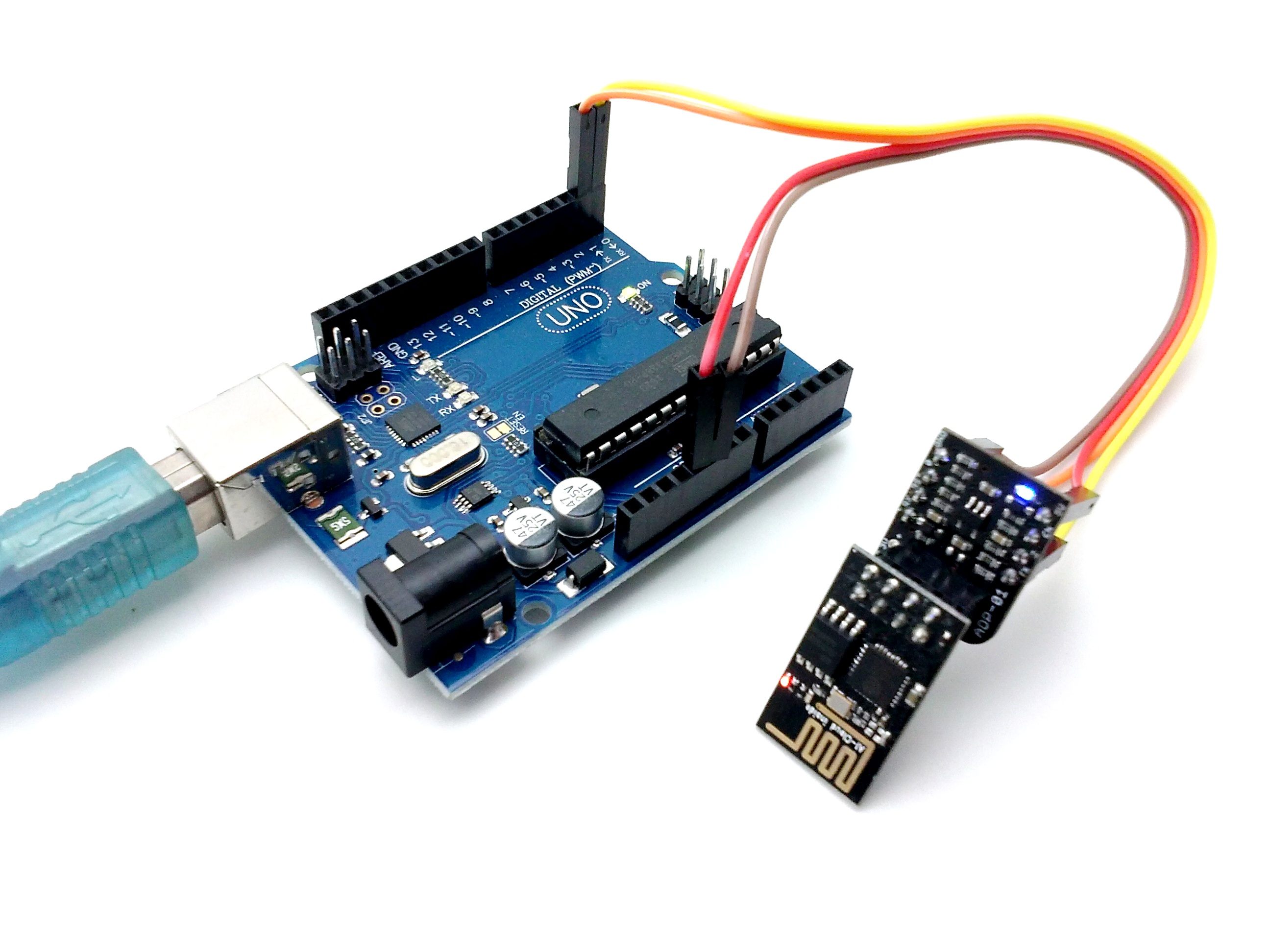
The WiFi module requires a power supply of 3.3V with current capability of at least 300 mA. Is not 5V tolerant!
So, if you use a 5V microcontroller board (such as Arduino UNO, which is a 5V board) it is not possible to connect the WiFi module directly, but you need an external interface which regulates from 5V to 3.3V and translates the logic levels 3.3 <-> 5V for the other logic pins (TX, RX, etc …).
To simplify the connection of our Wi-Fi module with any 5V board (like Arduino), we designed the ADP-01 Breadboard adapter.